 | This page is still under construction. |
Atmel Ultrasonic Ranger
Introduction
This page documents and design and implementation of an ultrasonic range finder. The main reason for taking on this project was to gain experience with the Atmel 8-bit microcontrollers. Before starting this project I already had plenty of experience with various microcontrollers and processors, so getting started with the Atmel microcontroller was straight forward enough. The features offered by all the different brands of microcontroller are reletivly similar e.g. USART, Timers, ADC etc etc. One of the big advantages of using an Atmel microcontroller is that it is supported by the GNU GCC compiler. This compiler has a long history and is used by many systems, some of which include Linux and Motorola systems.
Project Theory
When the ultrasonic transmitter is fed with a 40KHz AC signal, it will generate ultrasonic sound waves. The sound waves then travel outwards at the speed of sound. When the sound waves hit an object, they reflect back towards the source and are in turn picked up by the ultrasonic receiver. As we know the speed of sound, we can convert the time of flight to a distance.The actual speed of sound is dependent on (among other things) the temperature. For the sake of simplicity, this project will assume the speed of sound is 1cm every 30 microseconds, which is approximatley the speed of sound at 20oC.
Hardware
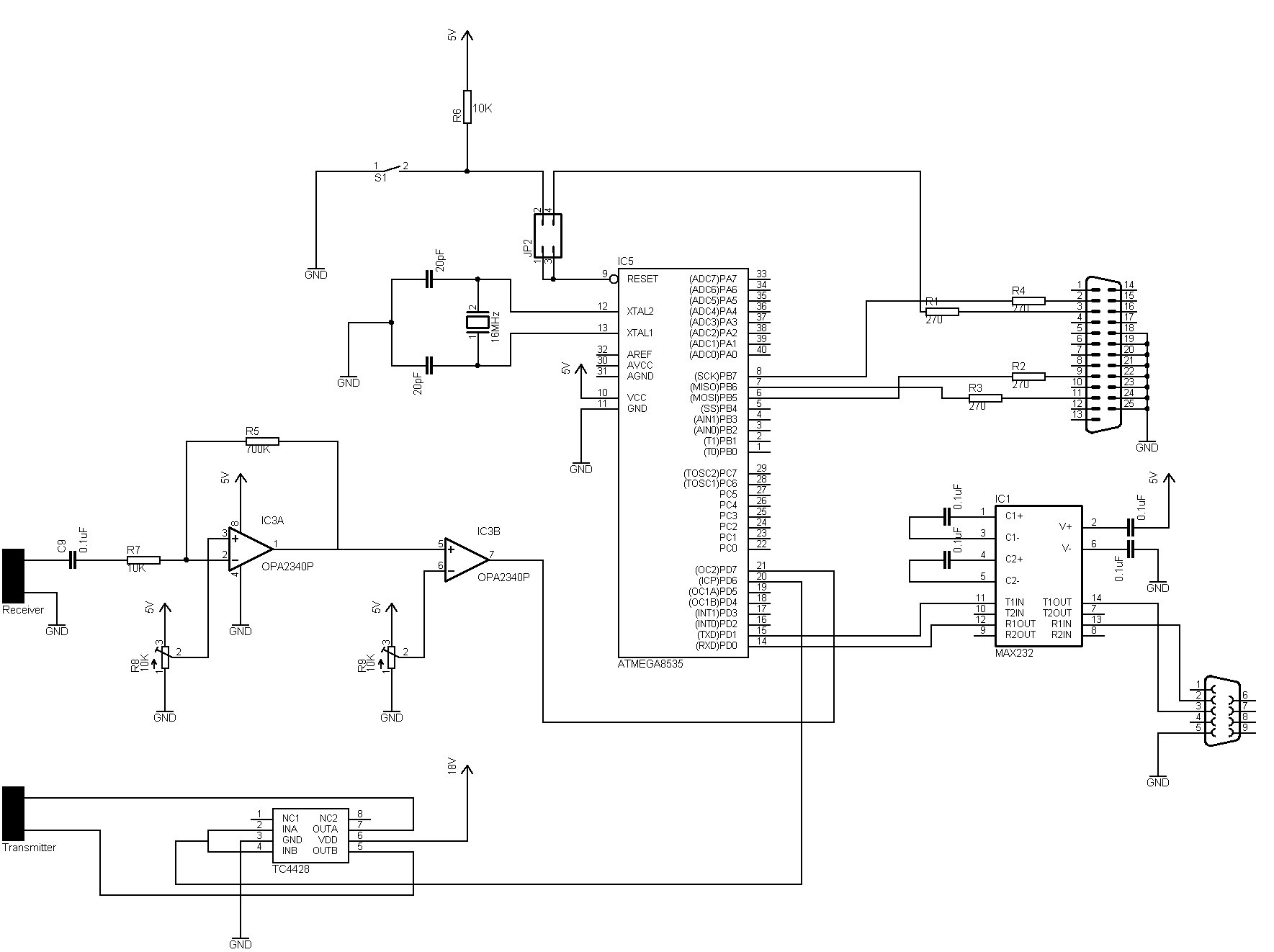
A 156KB schematic of the system can be viewed here (as you can see, drawing schematics isn't my strong point). The schematic excludes the 2 voltage regulators and the voltage doubler. They are instead, shown below.
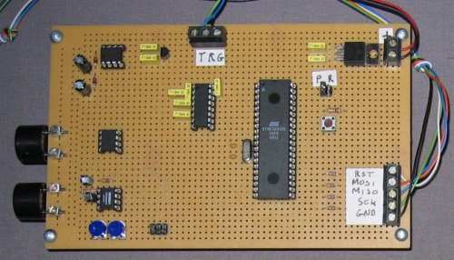
The project is made up of the following hardware components:
 | Atmel ATMEGA8535 Microcontroller |
| This microcontroller was picked at random, rather than on merit. It can run at maximum speed of 16MHz and it contains most of the features found in other microcontrollers. This project is fairly undemanding in terms of processing power so pretty much any of the Atmel microcontrollers would be suitable. | |
| SP12 Programmer |
| The microcontroller is programmed via the parallel port with a simple homemade SP12 cable. See the main schematic for details. | |
| HIN232 RS232 Transmitter / Receiver |
| Identical to the popular MAX232, but cheaper. This allows me to send the measured distance to the PC. | |
| Inverting Amplifier (Op-Amp) |
| The signal from the ultrasonic receiver is in the millivolt range and as such needs amplifying before it can be processed. The inverting amplifier is setup to amplify with a factor of 70. A trimmer could be used if you wanted to change the gain based on the application. | |
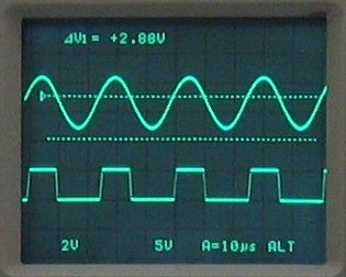
| Comparator (Op-Amp) |
| The output from the inverting amplifier is in the form of a low voltage sine-wave. The comparator converts the low voltage sine-wave to a 5V square wave (or something very similar), which is suitable for the microcontroller. The following scope capture shows the output of the inverting amplifier and the output of the comparator (note the voltage levels).
| |
| MOSFET Driver (TC4428) |
| A MOSFET driver converts the 40KHz 5V square wave from the microcontroller to a 40KHz 18Vp-p AC signal for the transmitter. There's lots of ways to generate the AC signal, this method is one of the simplest. For higher voltages a small transformer would probally make a better choice. | |
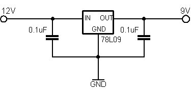
| Power Supply |
| The power supply unit consists of a 5V regulator, a 9V regulator and a DC-DC Voltage Converter. The DC-DC Voltage Converter doubles the 9V supply to 18V (or close enough). This 18V supply is then used by the MOSFET driver to generate the transmitters AC signal. | |
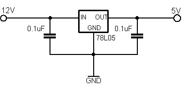 5V Regulator | |
 9V Regulator | |
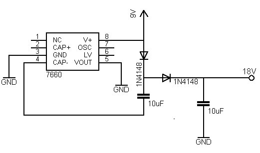 Voltage Doubler | |
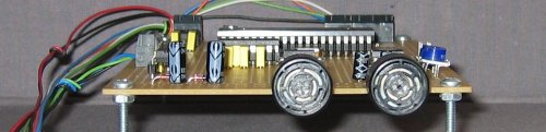
| Ultrasonic Receiver / Transmitter |
| A seperate receiver and transmitter has been used for simplicity. The next verion will have a single transducer. | |
Programming the Device
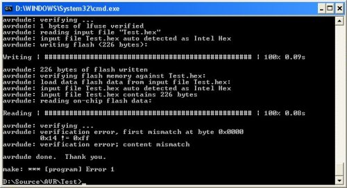
The microcontroller is programmed via the parallel port with a homemade SP12 cable (see the main schematic). The software used to download the hex file to the microcontroller is AVRDUDE. AVRDUDE is command line driven so it can be called directly from the makefile. nbsp;See the makefile for the paramters used.Every now and again AVRDUDE will report a content mismatch error; see the following screen capture. Some people on the Internet have experienced the same problem, which might be down to parallel port timing issues. While the microcontroller was running off the internal oscillator the error was quite common, but now it runs off an external oscillator the problem has pretty much gone away. If you get this error , you should just keep trying until it works. I've tried to find the ISP specification so that I can write my own programmer (it can't be that hard if you support only a single device and programmer), but as of yet I cannot find it. The AVRDUDE code is open source, but reverse engineering it seems like a lot of trouble to fix a rare error.
Source Code
I've noticed a couple of mistakes in the source code. I've setup the PWM chanel incorrectly (next time I'll read all of the data sheet). Although it still produces the required 40KHz signal. From the logs I can see that quite a lot of people have downlaoded the source code. It does work exactly as it should, but if try to change the PWM frequency via the source code it might fail. I'll upload the fixed code sometime soon. If you need help with the source then send me an email.Here's the source code as HTML.
Here's (UNDER CONSTRUCTION) the makefile as HTML.
Here's (UNDER CONSTRUCTION) the source code and makefile as a zip file.
Implementation
The system works by generating 5 40KHz pulses and timing how long it takes to receive an echo.
| Transmitting |
| The ATMEGA8535 contains a PWM (Pulse Width Modulation) module, which is used to generate a 40KHz square wave. The square wave is then converted to an AC signal by the MOSFET driver. The PWM module increments a counter in accordance with the external crystal. When the counter reaches its top value an overflow interrupt is generated. When the overflow interrupt occurs, the microcontroller increments a pulse counter and if the correct number of pulses have been generated, the PWM module is stopped. | |
| Receiving |
| When the PWM module is started the microcontrollers internal Capture/Compare module is also started. The Capture/Compare module will continue to increment an internal timer (in accordance with the external crystal) until either a rising edge is detected on its input or the timer overflows. The Capture/Compare's input is connected to the output of the comparator. Should a rising edge be detected (echo received), the timer is stopped and the value is converted to a distance. Should an overflow occur, the timer is reset and it is assumed no echo will be received (out of range). A 16MHz crystal is used by the microcontroller, which is too fast for the Capture/Compare timer. As a result a prescaler of 64 is used to slow it down. | |
| Calculating Distance |
| The Capture/Compare timer is setup with a prescaler of 64. As a result, it increments every ((1/16MHz)) * 64 seconds, which can be translated as once every 4 microseconds. Assuming the speed of sound is 1cm every 30us, the total distance travelled by the sound wave is ((timer_value * 4) / 30) centimeters. Because the sound wave has to go out and then back in, the distance travelled is equal to (((timer_value * 4) / 30) / 2) centimeters, which is equal to (timer_value / 15) centimeters. So, to convert the time travelled to distance just divide the timer by 15 (how easy is that). | |
| Notes |
| It's important to have a delay between receiving the echo and generating the next series of pulses. This can best be seen in the following screen capture, which is from a logic analyzer. The top channel represents the 5 pulses (square wave) sent to the MOSFET driver and the bottom channel represents the output of the comparator. | |
 | |
| As you can see, the echo arrives followed by a second echo, which is due to the sound waves reflecting backwards and forwards more than once. If you started a second series of pulses too early you would most likely detect the wrong echo. Having a delay between receiving and transmitting just allows everything to settle. | |
| In some cases the transmitted pulses maybe picked up by the receiver. This is shown by the following logic analyzer capture. Again, the top channel represents the transmitter and the bottom channel represents the receiver. | |
 | |
| To overcome this, a small delay is necessary after the last pulse is sent. The length of the delay only needs to be small. |
Results
The results are quite impressive considering the simple circuit and code. The calculated distance is more accurate than I thought and noise causes no problems whatsoever (in my simple tests). The system can detect objects as close as 1cm and as far as 1.8 metetrs. A variable resistor has been placed on the comparator, which allows the switching level to be changed. This would allow detection over much further ranges (although I haven't tried it yet). The distance calculated by the device is output via the serial port. This allows the results to be displayed in HyperTerminal.This video clip shows how sensitive the device is. The scope in the background shows the transmitted pulses (top trace) and the received pulses (bottom trace). As can be seen, even the slightest movement of the device is easily detectable (it also gave me an oppurtunity to try out my new digital camera). If you assume the speed of sound is 1cm every 30us, then sound travels 1mm every 3us (3000ns). The time of 3000ns may seem short, but the microcontrollers internal timer can increment every 62.5ns (1/16MHz).