SSTC Construction Diary
Day by Day Progress...
Monday 4 April 2005
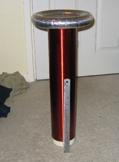
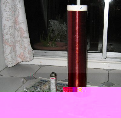
I've been experimenting with my digital cameras settings and it can in fact take really good photos. Here's a sample:
It's got a lot of different options which I'll try out tomorrow. I might buy some light yellow cardboard for a background. It would also be good to have a measurement stick next to the top load. I'll then take some nice photos.
I haven't given auto-tuning much more thought. I'll order some bits this week and see what happens.
I almost forgot to mention that I hammered a few feet of copper tube into the ground. Tomorrow I'll use it as an RF ground.
Sunday 3 April 2005
Although the PIC worked on the bench I noticed it kept resetting when attached to the coil. I put some extra decoupling capacitors on the reset and power lines and the resetting stopped. However, and quite interestingly, the Tesla coil now drastically under performs! Could it be that when the Tesla coil was resetting the original AVR microcontroller it was infact turning the control circuitry on and off at its resonant frequency, or in other words, auto tuning itself? I've removed the decoupling capacitors from the PIC microcontroller but the coil is still under performing. Although the startup sequence of the PIC and its crystal are different to the AVR. I'm going to put the AVR microcontroller back on the control board. It'll be interesting to see how the coil performs.
UPDATE
As suspected the Tesla coil, now back with the AVR microcontroller, produces large arcs! Even though the bridge is still being driven at 200KHz which was exactly the same as with the PIC microcontroller. So could it be that the Tesla coil is resetting the control circuitry at its resonant frequency? That would certainly explain the large continuous arcs. Even when turns are added and removed the coil still performed well.
Friday 1 April 2005
The AVR microcontroller is playing up. Even the most basic of code is failing to work as it should. Even when the controller is run from a bench top supply (with the Tesla coil turned off) it fails to work properly. Although I suspect interference from the Tesla coil will be a problem, the current failures are happening while the coil is turned off. At first I thought it was to do with the gcc compiler optimising my code in some strange way, but I've turned off optimisation, used volatiles throughout, and included asm volatile("nop") in all loops. I still can't find the cause of the problem. I've even checked the assembler output from the compiler and it looks correct. The symptoms don't look like hardware problems on the circuit board. I'm wandering if the AVR microntroller is damaged. It's taken quite a beating over the last few months as I've been using it on other projects. Could the Tesla coils magnetic fields have caused permanent damage? I've got some spare PIC microcontrollers that I'm thinking of using instead.I've been trying to get auto-tuning to work, but the problems with the microcontroller have been holding me back. My current design for auto-tuning is to use an antenna to pick up the coils resonant frequency, use a comparator to convert it to a square wave, and then have a tri-stated buffer between the comparators output and the push-pull system. The microcontrollers PWM signal goes to the push-pull system which drives the bridge. To start with the microcontroller generates a PWM signal and monitors the comparators output. When the microcontroller detects some edges coming from the comparator it stops its own PWM signal and then enables the output of the buffer, which allows the comparators output to go directly to the push pull system. So basically, the microcontroller starts the Tesla coil and then lets the antenna feed back take over. In theory it should work.
I put around 90V into the Tesla coil today and the resulting streamer was probably over 12 inches long! Although it was quite thin. I've got a video which I'll upload later. As soon as I turned the video and coil off the smoke alarm, which was located directly above the coil, went off!
The smell of ozone actually gets quite strong, even for short low powered runs, so good ventilation is needed. It should be noted though that humans can detect very small amounts of ozone. One of the effects of ozone on humans is a dry mouth and throat. For the past few days I've had a very dry mouth and throat! Although this is probably just a coincedence. I've put some info on ozone generation on a new Tesla webpage I'm making.
UPDATE
PIC to the rescue... I decided to replace the AVR, which I'm pretty sure was damaged, with a PIC (PIC16F74). I choose that particular micrcontroller as I already have it and it has the same number of pins as the previous AVR. Once the PIC was in place I rewrote the firmware for it, this time in PIC assembler, but I included extra support for the auto-tuning. I did a few test runs with the PIC and new firmware from my bench top supply (e.g. without the Tesla coil) and it worked first time! When the PIC starts up its PWM channel takes control of the bridge and the comparators signal is blocked via a tri-stated buffer. When the PIC detects 200 rising edges from the comparator it stops its PWM signal and asserts the output enable of the tri-stated buffer. This results in the comparators output from taking control of the bridge. On the bench it works well. Initially the bridge is running at 200KHz, but by touching the antenna I can take control and run the bridge at 50Hz (e.g. the mains frequency).At the moment the PIC is just counting rising edges from the comparator. But, if need be, it can be programmed with more advanced signal processing, which could filter out background noise etc.
Wednesday 30 March 2005
This webpage was becoming a bit cluttered so I've made some changes. New entries are now at the top of the page and the maths section and introduction have been removed. I'm creating a new webpage which will give more of an overview of the coil (pictures, videos etc). I'll put the maths section on the new page and the introduction has been rewritten. I've still got more changes to make to this page.
UPDATE
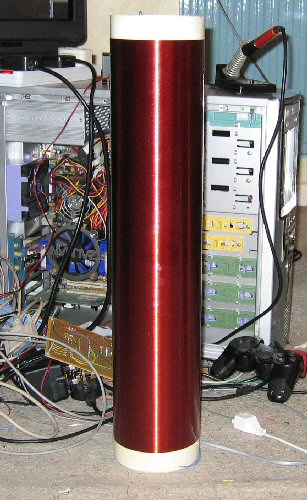
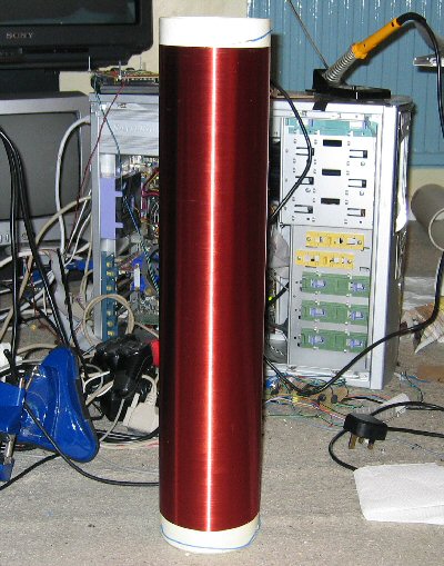
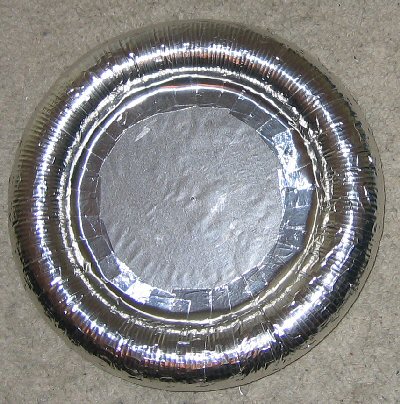
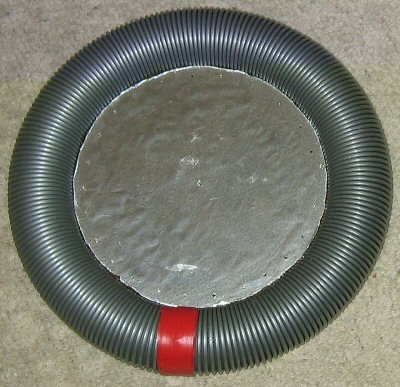
I've finished the new larger topload. Here it is:
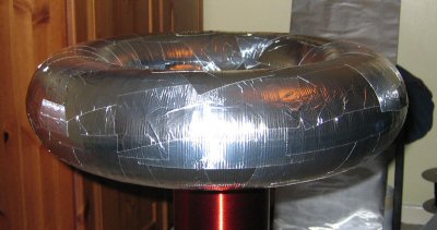
The camera flash has made it look quite patchy, but in normal light it's not really noticable. Initially I think the new top load will be too big, but it's worth experimenting with. I can't use it yet as I'm still performing tests with the smaller top load. I've also got to recalculate the resonant frequency as the extra capacitance will make quite a difference.
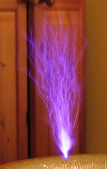
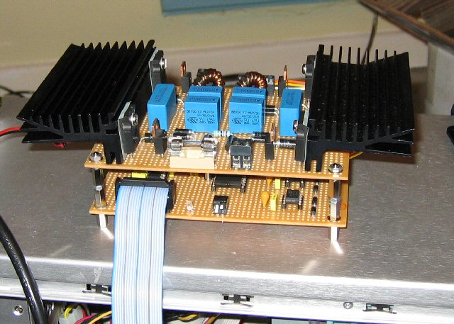
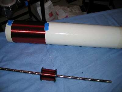
I've been performing more tests with different primary windings. I'm now getting bushier arcs. I'm still in the process of setting up a new webpage with pictures and videos of the tuning process. Here's a picture in the meantime.
Tomorrow I'm going to have a go at putting together a self tuning system. Rather than buying the ideal parts I'm going to use parts I already have. Hopefully they'll be okay, but if not, I will order the necessary components. I'm going to use an antenna going to a fast comparator. The microcontroller will monitor the output of the comparator and when it detects an alternating signal (e.g. the coils resonant frequency) it will switch the comparators output to the H-bridge. Should the comparators signal disappear for any reason the microcontroller will turn it's PWM signal back on. It sounds to me as if it will work, but we'll have to wait and see.
Tuesday 29 March 2005
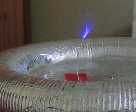
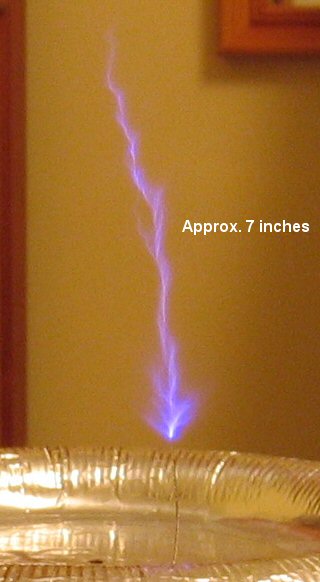
Today I bought some aluminium ducting. I can use this to create a much bigger top load. Generally SSTC's don't perform well with large top loads, but I think it's worth experimenting with. I'll construct the top load over the next few days.Here's a video of the new large arc (< 500KB):
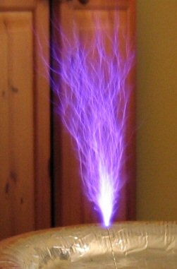
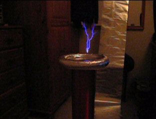
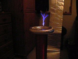
Here's 2 interesting stills from the above movie. You can see the RF ground in the background. The arcs in the pictures are over 7 inches long (they will get much bigger).
Monday 28 March 2005
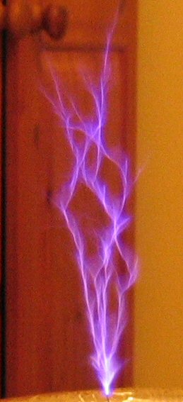
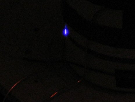
The emergency blanket RF ground still arcs over. It only does it some of the time though. It might be due to the fact that the foil on the blanket is very very thin. I've now replaced the blanket with aluminium tin foil, which is much thicker. I'll see if it also arcs. Interestingly, the arcs from the top load aren't as good with the tin foil RF ground as they are with the blanket. Although the blanket is bigger than the tin foil. Here's a small video clip of the RF ground arcing (turn the volume up to hear it):Here's a picture of a small arc coming from the top load (they will get much bigger):
UPDATE
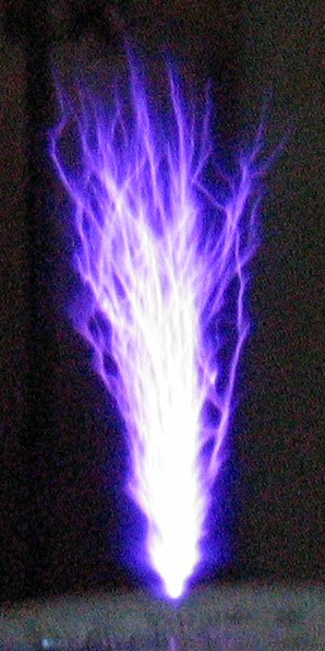
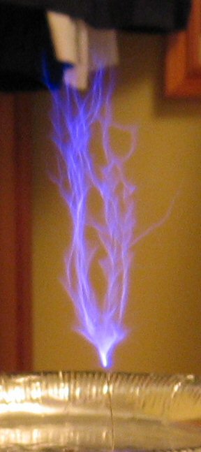
BIG RESULTS. I decided to rewind a new primary with 25 turns and then remove the turns one at a time while recording the results. I kept the frequency at 200KHz and recorded the results at input voltages of 40V and 80V. With 20 turns at 80V the arcs coming from the break out point were really big. I would estimate they were around 7 inches long, which isn't bad for an out of tune coil running at a low voltage. I was quite suprised (I would say shocked, but that's probably a bad choice of words) when the arc first appeared. At 40V the arc was very loud and powerful but was quite short. As I turned the voltage up it was getting much louder but seemed to stay at the same short length. Then suddenly, as I got closer to 80V, the big long arc appeared. It kept making a popping noise, which I think is a result of being out of tune. I could also smell what I think was ozone. The ozone smell was suprisingly strong considering the coil hadn't been running for long. Here's a photo of the long arc:
The photo doesn't really do the arc justice. In real-life the arc had a much sharper, brighter, appearance. I'll experiment with the settings in Paint Shop Pro to see if I can get closer to the original appearance.
As I'm now getting decent results I'll setup another webpage, which will contain more of an overview of the Tesla Coil, with results of various setups and videos. I'll still keep this construction diary going though, as I've still got more tuning to do. Ultimately, when the coil is in tune, the arcs should get much bigger for the same voltage (80V). I'm yet to get near to the maximum voltage.
Sunday 24 March 2005
I've flattened out the RF ground blanket and now the arcs are appearing from the top load via the break out point. The top load arcing starts at around an input voltage of 10V, which is quite promising. So far, with the top load attached, I've turned the input voltage up to around 40V. For the sake of the MOSFET's, I want the coil intune before running at the maximum voltage.I'm now going to concentrate on tuning the coil. My marker voltage will be 40V and I will stick with the primary coil being wound on top of the secondary. I will also stick with the current top load. The two properties I can experiment with are bridge frequency and primary turns. The first thing I start changing is the bridge frequency. I can do this by sending commands to the microcontroller from my laptop.
Friday 25 March 2005
Today I bought an emergency camping blanket, which I've attached to my wall. This then makes up the RF ground. I also decided to attach the top-load to the Telsa Coil with a small piece of wire acting as a breakout point. All other settings remained the same (in otherwords, the coil is still out of tune). During the first test I turned the variac up to ~40V and was suprised to see an arc coming from the top load. It was very bright and probably just under 2cm long! It made quite a nice noise as well. As expected, the extra capacitance of the top load makes a big difference.During the second test run I turned the variac up to around 20V and then I heard a much louder continuous arcing noise, which wasn't coming from the break out point. The emergency blanket is reflective like tin foil and I had the lights turned down so I could see the resulting arcs. This time though I couldn't see where the arcing was coming from, but I could see lots of bright reflections coming from the emergency blanket (RF ground). I quickly turned the variac down and unplugged the coil. I then inspected the coils looking for any visible damage. Everything seemed to be okay. Where was the arcing coming from?
To find out more about the arcing I decided to do a third test. This time I set my digital camera to video the back of the coil. When I turned the variac up to around 10V I noticed big arcs running over the RF ground! The Tesla Coil is attached to a steel rod via some thick copper wire. The steel rod is then placed on top of the RF ground. The arcing was happening between the steel rod and the RF ground. It's very bright and very loud. Suprisingly, and most worringly, the arcing has burnt the emergency blanket! I'm pretty sure the arcing was due to the crumpled blanket, which creates break out points.
Thursday 24 March 2005
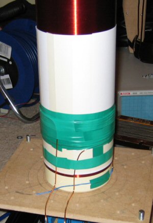
Here's the new primary coil (the white is paper is the primary coil is held in place with insulating tape):
I've been running it at ~100V and the primary arcs to the secondary. Here's a picture of the arc:
I think that's good news as it shows the H-bridge is working. I've used very little insulation between the primary and secondary so the arcing isn't that suprising. I'll just increase the insulation.
UPDATE
THE FIRST SUCCESS. I replaced the primary coil with 15 turns of new copper wire which has heavier insulation. That's stopped the primary to secondary arcing. I'm now getting arc's from the secondaries break out point (the coils first light)! Albeit, they are only 5mm long. I haven't attached the top load yet, which should improve things, but I think the reason for the small arcs is mostly due to tuning. I was running the coil at ~110V to get the first arc's, but I don't want to whack the voltage up until I'm confident about the tuning, as poor tuning could damage the (expensive) MOSFET's. Tomorrow I'll experiment with different primary coil configurations. Here's a picture of the first arc (it's actually a V shape in real-life and much more visible):

I'm not using the house ground as an RF ground. Instead, at the moment, I'm using a couple of meters of tin foil which I've attached to my wall. I might by an emergency blanket, as used by campers, and use that as an indoors RF ground. The blankets look metallic and I assume they're fairly strong. For outside tests I might hammer some copper pipe into the ground (a few feet long).
I'm treating the first small arc's as a positive, rather than a negative. It proves that the coil is working, even if it is out of tune. I haven't really put any thought into the primary coil, which explains the poor tuning, but it seems high coupling is the way to go. The new primary setup I have is easy to experiment with. The microcontroller, without shielding, hasn't failed yet.
Wednesday 23 March 2005
I've been running the coil from the mains at ~100V. I didn't get any output from the break out point so I think the coupling is too low. I'm going to wind another primary coil directly on top of the secondary. I'll just use a quick setup until I get an optimum output.
Tuesday 22 March 2005
Finally some progress. The new MOSFET's have arrived and are now fitted. The H-bridge is now working exactly as it should. I believe all the initial problems were due to 2 mistakes in connecting one of the gate drive transformers. The mistake was blowing the fuses and damaging the components. They were soldering mistakes rather than design faults. Anyhow, it's all fixed now and the current draw and output is correct. Tomorrow I'll do some mains testing.
Saturday 19 March 2005
I ran the H-bridge with the new schottky rectifier and the current draw was still massive. After some more investigation I discovered one of the gate drive tranasformers was wired up incorrectly! I fixed the wiring and continued the tests. The current draw was still massive! I decided to check the 2 MOSFET's, which were connected to the incorrectly wired up GDT, and they've failed! They now measure a dead short between the gate and drain, and between the gate and source. I can only assume it was due to the incorrectly wired GDT, which was probably the cause of the blowing FET drivers, but I'm still susprised at the failure of the MOSFET's. After all, all the tests I've done have been low powered for very short durations. I'll order the replacements on Monday (another �30 order) and they should arrive on Tuesday. This time I'll order plenty of replacements for all of the parts. I'm 100% confident that all the problems with the H-bridge have now been found. The other half of the H-bridge, with a seperate GDT, works as it should.
Friday 18 March 2005
Problems problems problems. The current draw while running the H-bridge from my desktop supply was massive (enough to blow several fuses). Also, the signals coming from one the gate drive transformers was also incorrect. Initially I thought this might be the cause of the high current draw (incorrectly switching the MOSFET's). After desoldering the GDT and much buzzing out the cause of the problem was found. It was actually a failed schottky rectifier. Maybe it failed from the short a couple of days ago, but either way, it was the cause of the high current draw and the fuses blowing. Luckily I had a replacement diode which I can fit. I assume this was also causing the poor signals from the GDT (didn't really need to desolder it). I'll put everything back in place by tomorrow and then I'll perform some more tests. I can see no reason why it shouldn't work now. The new push-pull system is working well and hasn't failed yet.
Tuesday 15 March 2005
After much desoldering, soldering, why doesn't it work, desoldering, and resoldering, I finally have the push-pull system in place. I just modified the original controller circuit, rather than constructing a new one. It looks a bit of a mess with the now unused heat-sink holes and desoldering marks, but that's okay. Once everything is working I'll remake the controller circuit. Initial tests show the new push-pull system to be working. It's also very cheap, which was one of the main reasons for choosing it. The voltage levels are correct, but one of the transistors gets very hot (hot enough to burn my finger). I've measured a bit more ringing with the push-pull setup. I can probably fix this with a resistor. Tomorrow I'll do more low powered tests. I have loads of spare transistors and fuses, so I hope to make some progress.
Monday 14 March 2005
I've ordered the the parts to make the push-pull system. I also bought loads of replacement fuses.
Sunday 13 March 2005
I'm still not sure why the fuse is blowing, but I decided to lower the controllers frequency down to 40KHz. I was also a little concerned about the 12V regulator as I don't think it's beefy enough. So, I attached some terminal block to the controller PCB and then connected the FET drivers power rails to it. Now I can power the FET drivers directly from my high power bench top supply. The 12V regulator is not attached to anything now. I also cut the FET drivers heat-sink down to size and drilled some new holes in it. It now fits better on the controller circuit board, which results in a tight fit to the FET drivers.Over the day I've been running the controller circuit without the H-bridge. I then attached the H-bridge and powered up the controller circuit, without any power being applied to the H-bridge, and 2 more of the FET drivers failed (including the one I replaced). That's �10's worth of FET driver! Interestingly, the 2 that failed are attached to the same gate drive transformer. And the one that failed a couple of days ago was also attached to the same GDT. Could ringing be the cause of the failure? Well, I didn't notice some ringing, but I wouldn't have thought it was enough to damage the FET drivers. Maybe I'm wrong though. Anyhow, the FET drivers are too expensive to keep replacing, so I'm going to move over to a transistor based push-pull setup. At the start of the project I was planning on using a push-pull setup, but the FET drivers seemed like a simpler solution, so that's what I went for. I would continue to try and get the FET drivers working, but they're just too expensive. Especially when you consider the �20 minimum order. For the cost of the replacement FET drivers I can buy the push-pull transistors, as well as loads of spares (I'll also order some more fuses). I should be able to modify the controller circuit board to take the push-pull converters (2 of them). Although it will have some holes in it, which I drilled for the now unrequired heat-sink. I'll order the parts tomorrow and they should arrive on Tuesday.
Could the FET failures be related to the fuse blowing? Maybe, if the H-bridge MOSFET's aren't switching properly, due to ringing or dodgy FET drivers, then the fuse would blow. I'm 99% certain that the H-bridge contains no short circuits. I'll see what happens when I use the push-pull setup.
Saturday 12 March 2005
I did some low powered tests today and the fuse blew again. This time, however, the fuse blew at around 40V with lots of sparks. I then decided to remove the coils and attach the scope to the output of the H-Bridge. When I turned the power up to around 15V the fuse blew again (I think I'm going to need a lot more fuses).
Friday 11 March 2005
I've been running the H-bridge off a 15V bench top supply and the fuses keep blowing. After lots more searching I finally found the cause of the problem. It was indeed a short. The short has been fixed and now the H-bridge runs of the bench top supply without blowing any fuses. I've also fitted some extra resistors to the H-bridge, which provide a bit of extra protection.
Here's a picture of the current casualities. Hopefully, it won't get much bigger.
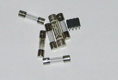
Running off the bench top DC supply, without any coils attached, everything looks to be working as it should. I'll do low powered mains testing tomorrow. I hoping for success.
Thursday 3 March 2005
I've ordered a replacement FET driver and it should arrive tomorrow. It's possible that the IC failed due to over heating. They do get very hot, so I'm going to attach a large heatsink. I'll do some more low powered tests tomorrow. Hopefully, the variac won't hum and the fuse won't blow.I think the coupling between the secondary and primary is too low. It's not too much of a problem to change it, but if it does need changing I'll experiment with various coupling ratio's using standard copper wire. That way I won't have to keep readjusting the primary coil form.
Friday 4 March 2005
The replacement FET driver has arrived and I've mounted a new heatsink on all 4 FET drivers. It's not a perfect fit, but it should do the job.
I performed another low powered test with the FET driver and the fuse has blown again. It must be a short. I'll do some more checks next week.
Thursday 3 March 2005
Today I performed the first low powered tests with both the secondary and primary coils in place. The results, a 5 amp quick blow fuse blew (the first sparks generated by the coil). It blew at just over 20V. So, it looks like something is shorting out, which would explain the humming variac. I replaced the fuse (I have loads of them) and attached some scope probes to the gate inputs of 2 of the MOSFET's. I peformed some low powered tests again and observed the scope traces. The first MOSFET was running okay, but the second was not, which is no doubtly the cause of the blown fuse. I'm yet to determine why the gate signal is incorrect. I initlially thought it would be a simple wiring mistake, but I've quadruple checked and the wiring seems okay. Could it be a problem with one of the gate drive transformers? I'll check later today.
UPDATE:
I've found the cause of the problems. One of the FET driver chips has failed. And at �5 each, I consider that a serious failure! I'm sure it worked originly, so it raises the question, 'how did it break'? I don't believe the power circuitry has caused the damage for 2 reasons:1) The gate driver transformers provide isolation between the power electronics and the sensitive control circuitry. Also, each of the connections between the gate driver transformers and the FET chips uses 2 schottky diodes, which provides further protection.
2) The power electronics has never been run with more than 20V. And the first time the power electronics was connected to the variac, the variac was set to 0V and it started to hum. Assuming the humming is a result of the damaged FET, the FET was damaged before the maximum of 20V was applied.
Each of the 4 FET drivers is powered from a 12V regulator and only 1 of them has broke. I've tried a replacement FET driver in it's place and it works fine, so that pretty much rules out a short circuit. At the moment I can't think what has caused the failure. They're designed for high current applications and should be able to withstand a lot of abuse. So far, the FET drivers have only been used a limited amount of times under gentle conditions.
As a result of one of the FET drivers failing, one of the gate driver transformers was only getting the top half of its AC signal. This explains the strange voltage on one of the MOSFET gate terminals and probally explains the fuse blowing.
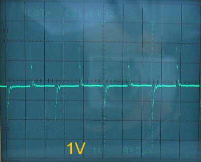
Here's a scope trace of the correct MOSFET gate terminal (I'll deal with the excesive ringing later):

And here's a scope trace of the incorrect MOSFET gate terminal:
I don't have any replacement FET drivers, so I'm going to have order one. I won't get the replacement until Tuesday. In the meantime I'll investigate the FET driver failure some more and I'll fix this webpage up. I'll also prepare a new webpage for the fully working coil.
Wednesday 2 March 2005
I did some low powered (20V) tests of the H-bridge and the control board. The H-bridge works as it should as does the control board. I had neither the primary or secondary coils connected. Tomorrow I'll do similar tests, but at a higher voltage, with both coils connected. The H-bridge worked first time and so needed to modification. I did notice some humming coming from the variac though, which I'll have to investigate some more.
Tuesday 1 March 2005
After much delay, I still haven't performed any low powered tests. I've remeasured the resonant frequency of the secondary coil and it is indeed 208KHz without a top load (pictures to be posted soon). The top load seemed to make little difference, but I'm yet to investigate this properly. I'm having some trouble measuring the primary coil resonant frequency and the coupling coefficient. At the moment, I'm not that bothered about the primaries resonant frequency. Not being able to determine the coupling coefficient is a bit worrying though. I can only find a single peak at 20KHz. Could this be the lower frequency of the coupling coefficient? It sounds very low to me. And where is the higher frequency of the coupling coefficient? I've searched upto 5MHz and cannot detect anything. Could this be a sign that the primary coils diameter is too big? I really hope not. During the measurements I'm using 2 470nF capacitors to emulate a primary capacitor. Maybe this is causing the problems. I have to do a bit more research on this.Interestingly, or should I say worringly, I connected the secondary coil to the function generator while it was about 1.5 meters from my PC. When I turned the function generator on it caused the modem to disconnect. I quickly turned the function generator off and tried to reconnect the modem. It wouldn't reconnect until I restarted the computer. This is bad sign for the SSTC's microcontroller. The function generator has a peak to peak value of 20V. The Tesla coil will ultimatley be running off several hundred volts and producing voltages in the tens of thousands. Maybe shielding will be needed after all.
Friday 25 February 2005
Well, it's been a while, but the function generator has now arrived. It's quite good except it doesn't have a fine tune control and it doesn't have support for FM. Other than that it's fine. I did a quick test by connecting it to the secondary coil and putting the scope probe near. The coil seemed to have a resonant frequency of 208KHz, which is close to the calculated value. I'll do more detailed tests over the weekend. I'm going to calculate the coupling coefficient which requires using the primary coil as well. I'll now definatley be able to perform the first low powered tests on Monday.
Saturday 12 February 2005
Here's the current state of the primary coil.

The copper wire, which makes up the primary coil, is very hard and is pretty difficult to get into shape. But the results look good.
Friday 11 February 2005
That's it, I've cut the primary coil holders to shape and put them in place with nuts and bolts. I've also wound the primary coil. The whole setup looks really good. I'll post pictures tomorrow. I've used 19 turns for the primary which I don't know is good or not. I can easily remove turns, but adding turns will mean having to buy more copper wire. Hopefully it should be okay.Pretty much all construction is now finished. I can now start low power testing. I'm still going to wait for the function generator before doing any tests. It should arrive next week.
Thursday 10 February 2005
I had a go at winding the primary and it's harder than I thought. The wire is pretty strong and it's too heavy to hold it's own weight. I've cut some MDF supports for the primary and they will be screwed in place tomorrow. They will include a slot which will hold the primary. I will probably do away with the paint bucket coil form. The MDF coil supports look really good and hoefully they'll be able to keep the primary coil in place.I'll wait for the function generator before doing any low power tests. I want to measure the resonant frequency first.
Tuesday 8 February 2005
The copper wire arrived today. I can now start winding the primary coil. I might make a different type of coil form.
Monday 7 February 2005
I called the copper cable supplier and they said it will arrive on Wednesday. I can then wind the primary coil. I may not wind the primary around the primary coil form. The copper cable should be strong enough to keep its shape, which wouldn't require a coil form. It would look really good as well.I've also bought a 5MHz function generator. I've been meaning to get one for a while now. It might arrive sometime next week. I could use it to determine the secondary coils resonant frequency.
Friday 4 February 2005
The isolation transformer has arrived and it's very heavy.

I also bought a half price 30m extension lead. It's rated for 13A and some of the wire will be used to power the Tesla coil. I'm still waiting for the 3mm copper wire. I sent the company an email but they haven't replied. They haven't taken any money from my account either. I'm wandering if the company is still in business. I'll deal with it next week.
Thursday 3 February 2005
I've ordered a 3KVA isolation transformer. It should arrive tomorrow. I've also sent an email asking when the copper wire is going to arrive.
Wednesday 2 February 2005
I'm still waiting for the 3mm copper wire to arrive. I think I might buy a 3KVA isolation transformer. It has lots of uses, one of which is running the Tesla coil.
Thursday 27 January 2005
Two of the diodes on the microcontrollers power supply where soldered in backwards. I've now desoldered and reversed them.I ordered a kilogram of 3mm diameter copper wire. This will make up the primary coil. It came to a massive �20 after postage and V.A.T. I decided agains't using regular mains cable (the copper cable should look good as well). I'm yet to do any calculations regarding the primary coil. I might do them, as well as recalculate the secondary and topload, tomorrow. Having the variac allows me tune the coil on a low voltage which should hopefully stop the expensive MOSFET's from blowing up.
Wednesday 26 January 2005
I've finished the base unit and it looks quite good. Here it is (excluding primary coil):

Tuesday 25 January 2005
After many hours of marking out, sawing, sanding, more marking out and drilling I finally had all of the woodwork finished. Once the sawdust had settled (I should really have done it outside) I got to work glueing and screwing it all together. I then stepped back and looked at my woodwork creation. It looked really bad. It looked so bad I didn't even take a photo of it. Tomorrow I'm going to cut 2 new MDF platforms and start again. My mistake was trying to make too complicated a structure. Tomorrows attempt will just use 2 MDF platforms with metal screw rod for legs (like the variac). The screw rod will allow for height adjustments and will be much simpler to put in place. I hope to have the base unit finished tomorrow.Now the varnish on the coil is completley dry it looks really good.
I should be able to perform my first coil test early next week (Monday or Tuesday). The results should be good. Here's the coil with the topload attached (it looks much better in real life than in the photo):
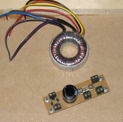
Here's the AC to DC converter (for the microcontroller) and the toroidal transformer. It's not much too look at really. It's just a bridge, fuse and cap.
Isolating my oscilloscope shouldn't be as expensive as I first thought. It would be really good to have attached to the H-bridge. I will probably try and get it setup.
Monday 24 January 2005
Bought some 21mm by 21mm pine wood which will make up the supports for the Tesla coil. I've cut some of it to shape. I'll do the rest tomorrow.All that's really left is winding the primary coil and performing the intial tests. I might just use mains cable for the primary coil. My initial tests will use a user settable frequency. I'll try auto-tuning once I know everything is working.
Sunday 23 January 2005
I drilled some holes in one of the MDF squares which allows me to screw the circuitry in place. I also made the AC to DC converter. This requires a small toroidal transformer which is also screwed to the MDF square.
Saturday 22 January 2005
I cut and sanded 2 squares out of MDF which will make the 2 platforms of the base. To one of the platforms I have mounted all of the electronics. This includes the AC to DC converter which I made today. The platform looks pretty good. Tomorrow I might buy the wood to make the legs and supports. That would then complete the base.My white spray paint can is empty so I couldn't spray the primary coil form. I may just continue sanding it as I don't want to buy anymore paint.
Friday 21 January 2005
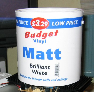
Didn't do much today either. I bought a cheap plastic pot of paint which will make up the primary coil form. I've cleaned the pot out and have sanded most of the advertising off. It's quite smooth and most of the advertising has gone. Tomorrow I will either continue sanding or I will just spray it with white spray paint. I've cut the plastic paint lid to the same diameter as the secondary coil form. This will be super glued to the secondary coil form tomorrow and it will allow the top load to be connected.
For the initial tests I might construct a larger top load. I could use aluminium ducting. A larger top load would reduce the resonant frequecy of the coil which would make life easier for the MOSFET's. I've still got plenty of aluminium tape.
I might start constructing the base tomorrow.
Thursday 20 January 2005
Didn't really do much today. I bought some MDF to make the base and I also ran the gate driver transformers with a frequency of 300KHz (much higher than I will need). The transformers could easily handle it. I've noticed that the MOSFET driver IC's get really hot . That does suggest that something is wired up incorrectly. I'll have to investigate further. I looked around for a primary coil form and the only thing I could find was a plastic pot of paint. I may buy it tomorrow and sand and clean it. I could then wrap the primary around it. I'm not yet sure what wire I'm going to use for the primary.Here's the completed boards connected together. The ribbon cable is for the SP12 programmer and the RS232 link.
Wednesday 19 January 2005
I've soldered in the gate driver transformers and I've buzzed out the H-bridge. I didn't find any problems. That completes the 2 circuits and some low voltage testing can take place as soon as I've wound the primary. I haven't given the primary any thought yet.I've ran the gate driver transformers at 100KHz and put scope probes on the MOSFET gates. Everything looked correct. This was mainly to check that 2 of the MOSFET gates were being driven 180o out of phase (it would be a bit silly to drive them all at the same time). The H-bridge has no mains isolation, so I can't use the scope while it's being powered. I would really like an isolation transformer but I don't want to spend anymore money after buying the variac.
Tuesday 18 January 2005
Here's the new heavy 20A variac. I used some threaded rod to make the legs.

Monday 17 January 2005
I've bought a large 20A variac. It was a lot of money, but it has multiple uses.For a quick test I wound a gate driver transformer with a turns ratio of 1:1:1 with trifiliar windings. I then programmed the microcontroller to generate a 100KHz PWM signal. The PWM signal was fed into the transformer and the 2 secondary outputs were measured on a scope. The results were as expected, which is good. Tomorrow I'll buzz out the untested H-bridge and fix any errors. With the soon to arrive variac I should be able to start some low voltage testing of the H-bridge.
Sunday 16 January 2005
Here's the current state of the coil.
It's looking pretty good. I'm still going to apply some more coats of varnish though.
I've done some research regarding the need to shield the microcontroller and it seems that it probally will be necessary. This might cause some complications. Although, having the microcontroller and H-bridge on different circuits might make things a bit simpler. I'm guessing that only the microcontroller will need shielding. I'll have to research this a bit more.
Saturday 15 January 2005
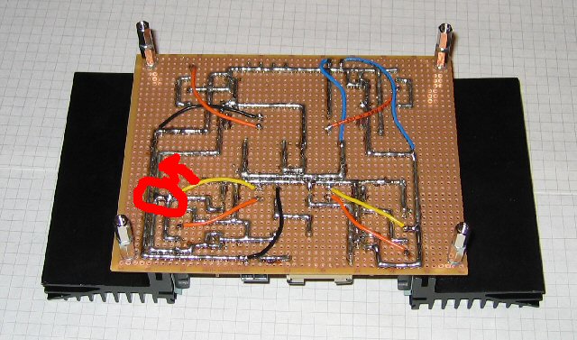
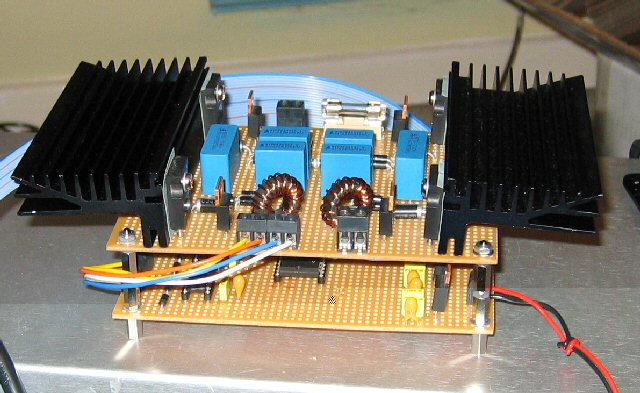
Here's the untested H-bridge and microcontroller circuitry. The H-bridge is missing the gate driver transformers and the microcontroller circuit is missing the IC's.
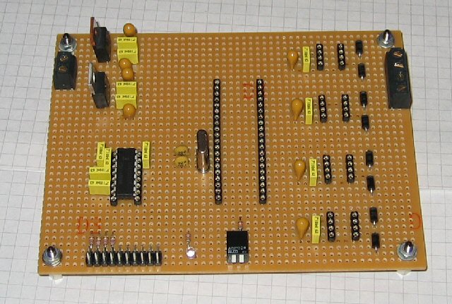

The 2 circuit boards screw together (the H-bridge on top of the microcontroller) to make a single unit.
The microcontroller board has an RS232 transceiver and an LED. The LED will flash at regular intervals to show that the board is working and the RS232 link is for feedback and control purposes. The RS232 interface is via the IDC connector which also provides an SP12 (AVR programmer) interface. The 2 piano switches are for reset and programming control.
Thursday 13 January 2005
I've ordered some more bits from RS. The order includes smaller toroidal ferrite cores (gate drive transformers) and spacers. I'm going to mount the driver circuitry under the H-bridge circuit.The H-bridge is almost finished.
Wednesday 12 January 2005
The coil is looking really good and I'm still applying coats of varnish. Each coat of varnish takes 24 hours to dry.I was worried that the wire on the H-bridge would fail under the high voltages. Also the wire was a bit thick for the board making placement difficult. So instead I've replaced the wire with solid tracks of solder. Hopefully it should do the job.
Tuesday 11 January 2005
I've finished rewinding the coil and it looks MUCH better. I've also applied the first coat of varnish.
Monday 10 January 2005
The look of the coil (with cotton) was really bugging me. So I've taken all the copper off (it took ages to get off) and I'm now going to rewind it (with new copper). I had to sand the coilform flat again and to be on the safe side I've applied another coat of varnish. I hope to have the coil rewound tomorrow.
Sunday 9 January 2005
The varnish is now dry on the coil and sadly the cotton is still visible. It's not too bad though. Thinking about it, I might have been able to burn the cotton off. I could have quickly waved a flame over the coil and the cotton would have burnt away. I'll continue applying coats of varnish.I'm now building the H-bridge.
Saturday 8 January 2005
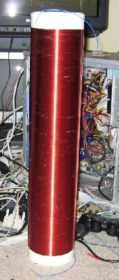
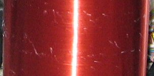
I've finally finished winding the coil. The coil looks good and is wound pretty tight. The only annoying thing is that cotton has become trapped between the turns. I'm not sure where the cotton has come from. I'll try and remove it all before applying the varnish. The first picture shows the coil and the second is a close up of the cotton. The white streaks in the first picture is the cotton, not gaps in the turns.
UPDATE
Sadly I couldn't remove the cotton. I've decided to now apply a coat of varnish. I'll apply quite a few coats. Hopefully the varnish will hide the cotton.
UPDATE
The first coat of varnish is starting to dry and the cotton isn't that visible. It's starting to look pretty good. Some extra coats of varnish should fix it.
Friday 7 January 2005
The third coat of varnish is dry and I've started winding the secondary coil.
It's quite tedious work and should be finished tomorrow.
Thursday 6 January 2005
The aluminium tape arrived today. I've used the aluminium tape to cover part of the toroid.
It's pretty smooth and very rigid.
I will probally start constructing the H-bridge tonight. I've got some doubts over the wire I'm going to use on the H-bridge. I don't want to buy anymore because it's too expensive. For now I'll stick with what I've got. I'll keep an eye on it during testing.
I've also applied a third coat of insulating varnish to the coil form. That maybe the last coat I apply before winding. I'll decide tomorrow once it's dry.
Wednesday 5 January 2005
The hoover hose, which I bought on eBay, arrived today.

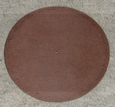
Now I can start making the toroidal top load. I've cut a circle out of hardboard to which I'm glueing some aluminium tin foil. I've also drilled a series of holes around the circumference of the circle. These holes are for the wire, which will hold the hoover hose in place (this is a method used by other coilers). The hoover hose will then be covered in aluminium tape (I hope the tape will arrive tomorrow).
I've applied another coat of insulating varnish to the secondary coilform. It takes 24 hours to dry. Tomorrow I'll either apply a third coat of varnish or I'll start winding the coil itself.
I've also placed another order with RS. The order includes heatsinks for the H-bridge MOSFET's and the MOSFET driver IC's. These items should arrive tomorrow. As soon as the order arrives I'll start constructing the H-bridge and the PWM driver. I need to start thinking about a base for coil as this has an effect on the circuit layout.
I'm definatley going to use an Atmel AVR microcontroller. The microcontroller allows for greater flexibility later on. I might ignore any shielding problems for now.
UPDATE
I've cut the hose to length and super glued the ends together. The red tape is just to keep it secure. I tried to hold the hose in place using wire through the holes, but it's very fiddly and I couldn't get it secure enough. So instead, I've just super glued the disk to the hose. It's pretty strong. Once the aluminium tape is in place it should be even stronger. It's very rigid, which I'm not sure I would get using the wire method.
Tuesday 4 January 2005
I seem to have forgot to order the heatsinks and the PWM driver IC's (I'm sure I ordered them). I've cut the secondary coil form to the correct height (50cm + 5cm) and I've now applied the first coat of insulating varnish (inside and out). Before applying the varnish I sanded coil form to a nice smooth finish. I'll probally apply 3 coats of varnish before winding the coil.I'm having second thoughts about the PWM driver circuit. I was going to use the common TL494, but this seems overkill for the simple job it has to do. I'm tempted to use the PWM channel of an Atmel microcontroller. The microcontroller would also allow for easy addition of extras, such as infra-red control. It could even be used to process feedback from the Tesla coil and adjust the PWM signal accordingly. Would the controller operate in the high magnetic fields? I'm guessing that some sort of shielding would be required. I'll have to research this a bit more.
Monday 3 January 2005
I've had a few practice goes at winding the secondary coil. To make things easier I bought some super glue, which should hold the wound coil in place. I also bought a small paint roller, which I will use to apply the secondary varnish.
Sunday 2 January 2005
I've bought a Dyson hoover hose and aluminium tape on eBay. This will be used to make the toroidal top-load.