Induction Heating
While researching transformer design and magnetic fields I came across a process known as induction heating. This seemed like an interesting feature which I decided to investigate further. It actually turned out that an induction heater had very strong ties to a SSTC (solid state Tesla coil). This page shows my results in constructing an induction heater.
I'm actually thinking that an induction heater would make an ideal hot plate for my chemistry experiments. Professional hot plates start at Ł250 and go upto several thousand. An induction heater could easily heat a metal plate upto several hundred degrees celsius and to implement temperature control would be fairly simple.
Technical Description
The actual workings of an induction heater are fairly simple. A high frequency alternating current is made to flow through a heating coil, which in turn causes an intense magnetic field to continually rise and fall. When a conductive object is placed within the alternating magnetic field eddy currents will flow through it. It is these eddy currents which cause the object to heat up.The high currents required for induction heating are generated by a self-resonating LC network. The current in the LC network is continually oscillating between the heating coil and the tank capacitor. At the same time a high frequency, low current power supply is continually feeding more current into the LC network. If the power supply is alternating at the resonant frequency of the LC network then the current induced in the LC network can reach very high levels.
A further advantage to switching the power supply at the LC networks resonant frequency is that the current during the switch will effectively be zero. This dramatically reduces the amount of heat that the MOSFETs have to dissapate. If the power supply is driven at the wrong frequency the MOSFETs would switch at high current points and would quickly fail.
The self-resonating properties of an induction heater are similar to that of a SSTC (Solid State Tesla Coil). Infact, the induction heater on this page uses the H-bridge and an old driver from my SSTC. The only noticable difference between an induction heater and a Tesla coil is that an induction heater generates high currents whereas a Tesla coil generates high voltages. The big problem with SSTC's though is that the resonant frequency is highly dependent on the surrondings and the resulting streamers, and is therefore continually changing. To deal with the SSTCs continually changing resonant frequency the SSTC driver often employs an automatic tuning system which effectively monitors the SSTCs resonant frequency and then adjusts the its frequency, and therefore the H-bridges frequency accordingly. Without automatic tuning it is likely that the SSTCs MOSFETs will switch at high currents and will therefore quickly overheat and fail. The resonant frequency of an induction heater is largely uneffected by its surroundings and therefore tends to stay fairly consistant through out its operation. As a result, it's perfectly acceptable to manualy tune the induction heaters driver.
Simulations
I'm a relative novice at SPICE simulations, but I've found the information gathered through simulations to be of great benefit. The simulations also provide a good mechanism for demonstrating the effect of driving the LC network at its resonant frequency.The following diagram shows the SPICE schematic of the induction heater with each component having the same value as my real-life heater (see the Current Setup section for more details on the real-life values).
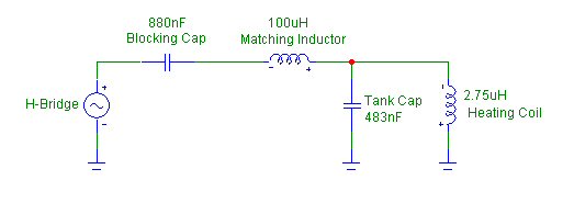
From the resonant frequency formula it is calculated that the above circuit resonates at 138KHz (1/(2*pi*sqrt(2.75uH * 483nF)). This can be confirmed in the simulation by peforming an AC analysis and on the real-life induction heater by finding the peek voltage across the tank cap.
 |
 |
The following graph demonstrates what happens when the circuit is driven at its resonant frequency. The blue trace represents the current in the heater coil and the red trace represents the current coming out of the H-bridge.

The graph clearly shows a small amount of current coming out of the H-bridge with a large amount of current building up in the heating coil.
If the circuit is driven at a frequency lower than its resonant frequency the current in the heating coil will fail to reach such high levels. As has already been mentioned, driving the circuit at a frequency other than the resonant frequency would put a great strain on the H-bridge MOSFETs and cause them to fail (this is not demonstrated in the simulations). The following graph shows the current from the H-bridge and the current in the heating coil with a frequency below the resonant frequency.

The same problems also occur if the circuit is driven at a frequency which is higher than its resonant frequency.

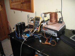
Current Setup
UNDER CONSTRUCTION
Results
UNDER CONSTRUCTIONMax temperature so far is 700 deg. C.
Check back soon...
| Home |